x_strategy_for_API

<!DOCTYPE html> <html>

<head> <meta charset="utf-8">

<script async src="https://www.googletagmanager.com/gtag/js?id=G-NG21EXTML9"></script> <script> window.dataLayer = window.dataLayer || []; function gtag(){dataLayer.push(arguments);} gtag('js', new Date());

gtag('config', 'G-NG21EXTML9'); </script> <meta name="viewport" content="width=device-width, initial-scale=1.0, shrink-to-fit=no"> <title>SpeakHDL</title> <meta name="keywords" content="FPGA, FPGA Prototyping, FPGA Tool, Voice Coding, procedural programming, FPGA Easy, VHDL, FPGA for beginners"> <meta name="description" content="A practical FPGA design tool that combines procedural programming using native VHDL with command-based programming"> <link rel="icon" type="image/png" sizes="16x16" href="assets/img/logo/favicon-16x16.png"> <link rel="icon" type="image/png" sizes="32x32" href="assets/img/logo/favicon-32x32.png"> <link rel="icon" type="image/png" sizes="192x192" href="assets/img/logo/android-chrome-192x192.png"> <link rel="icon" type="image/png" sizes="512x512" href="assets/img/logo/android-chrome-512x512.png"> <link rel="stylesheet" href="https://cdn.jsdelivr.net/npm/bootstrap@5.2.3/dist/css/bootstrap.min.css"> <link rel="stylesheet" href="https://use.fontawesome.com/releases/v5.12.0/css/all.css"> <link rel="stylesheet" href="https://cdnjs.cloudflare.com/ajax/libs/font-awesome/4.7.0/css/font-awesome.min.css"> <link rel="stylesheet" href="assets/fonts/fontawesome5-overrides.min.css"> <link rel="stylesheet" href="https://unpkg.com/@bootstrapstudio/bootstrap-better-nav/dist/bootstrap-better-nav.min.css"> <link rel="stylesheet" href="assets/css/doxy-override.css"> <link rel="stylesheet" href="assets/css/Footer-Basic.css"> <link rel="stylesheet" href="assets/css/Login-Form-Clean.css"> <link rel="stylesheet" href="assets/css/banner.css"> <link rel="stylesheet" href="assets/css/examples.css"> <link rel="stylesheet" href="assets/css/speakhdl-styles.css"> </head>

<body> <nav class="navbar navbar-light navbar-expand-md sticky-top navbar-top theme-outline" id="my-nav">

<button data-bs-toggle="collapse" class="navbar-toggler" data-bs-target="#navcol-2">Toggle navigation</button>

</nav> <article>

<section>
<header>

Creating an API for FPGA Hardware Development

</header>

Strategy for API Development

Attempting to create an API for FPGA hardware design is somewhat difficult because our abstractions and implementation are so tightly coupled. One thing to note when creating our API is that we are not changing the underlying complexity of FPGA design, we are trying to hide the complexity from the API caller by utilizing abstraction and structured levels of data organization. Due to our organizational scheme, we end up with very large data structures that we have to interact with.

Our challenge in trying to a creating a useable API for FPGA hardware development is threefold: 
  1. Understand the synthesizable HDL language features we have at our disposal
  2. Organize the data structures that we create in such a way that the end user can become the most productive
  3. Create procedure calls based on operations that can be used as building blocks in system design
Understanding the synthesizable HDL language features that we have at our disposal is most important because it will influence the data structures we create and the procedure calls we define. Interestingly enough, the VHDL language supports function and procedure overloading. The ability to have a single procedure call that can accept parameters of different data types and do different things based on that data type knowledge at compile time is extremely beneficial. Using this language feature to our advantage helps us to decrease the number of different procedure call names that the user will need to interact with.

Because, creating an API is more of an art than a science,  there will be instances where we could approach our data structuring in multiple ways.  Since our overall goal is to be come more productive FPGA developers, we describe the strategy we use for creating the API for our design pattern.
  • Treat everything as a synchronous state machine
  • Ensure the default behavior is the most useful behavior
  • Prefer indexing an array over a creating a new signal
  • Use aliases for readability
  • Use integer data types for index, count, and state
  • Have productivity come for free
<aside class="d-flex align-items-center aside-xxx">
Added Value
From a productivity stand point. We would rather end up with a small number of large data structures than a large number of small ones

</aside> <aside class="d-flex align-items-center aside-xxx">

Added Value
Procedure overloading is a form of static polymorphism. Also is benefical over verilog

</aside>

Everything Is A Synchronous State Machine

In development of the design pattern, we started using a state machine as a facade object.  Now, we take the state machine concept a step further and begin treating the application modules as event driven state machines. By doing this, it makes sense to keep the signal nomenclature explicit to make it clear that when using the design pattern, we are dealing with state machines. Thus our API procedure calls explicitly call out the next state logic and state register logic as their last two mandatory parameters.

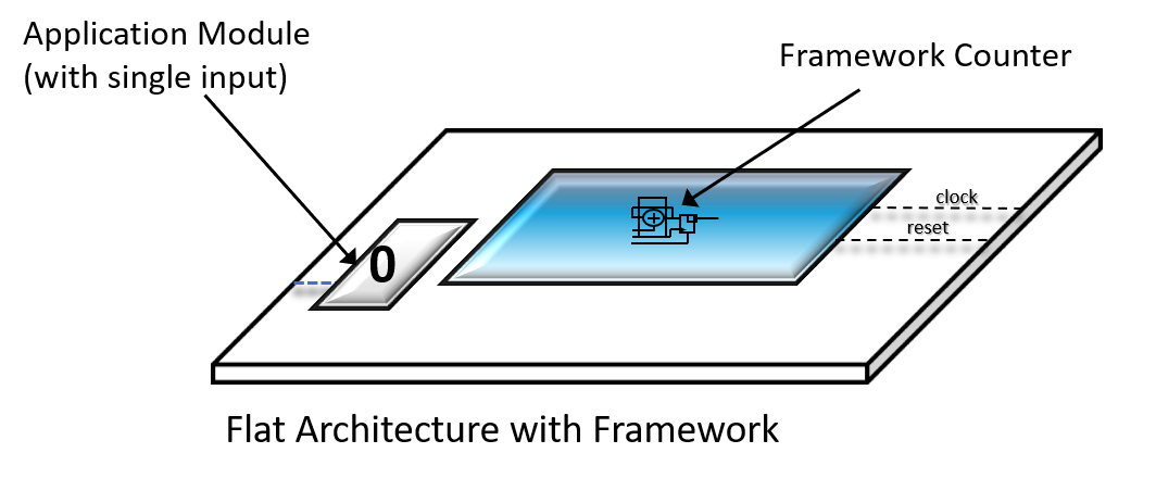
To motivate our rationale as to why we should treat an application module as a state machine, let's start with an example where an application module has exactly one input pin that is used as the count enable to a framework counter
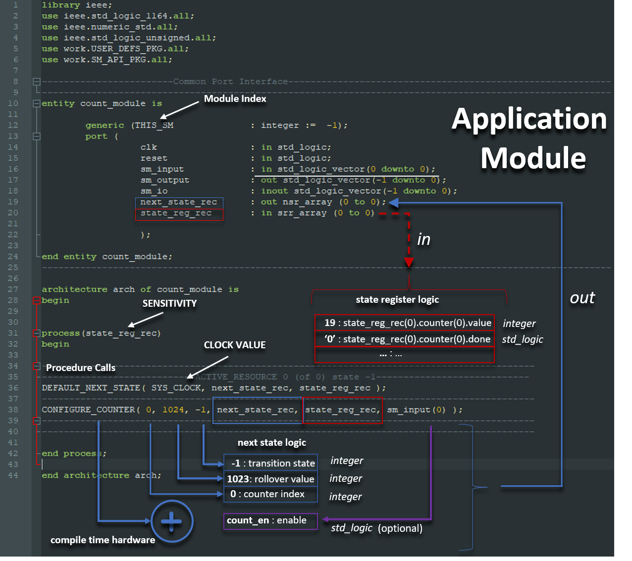
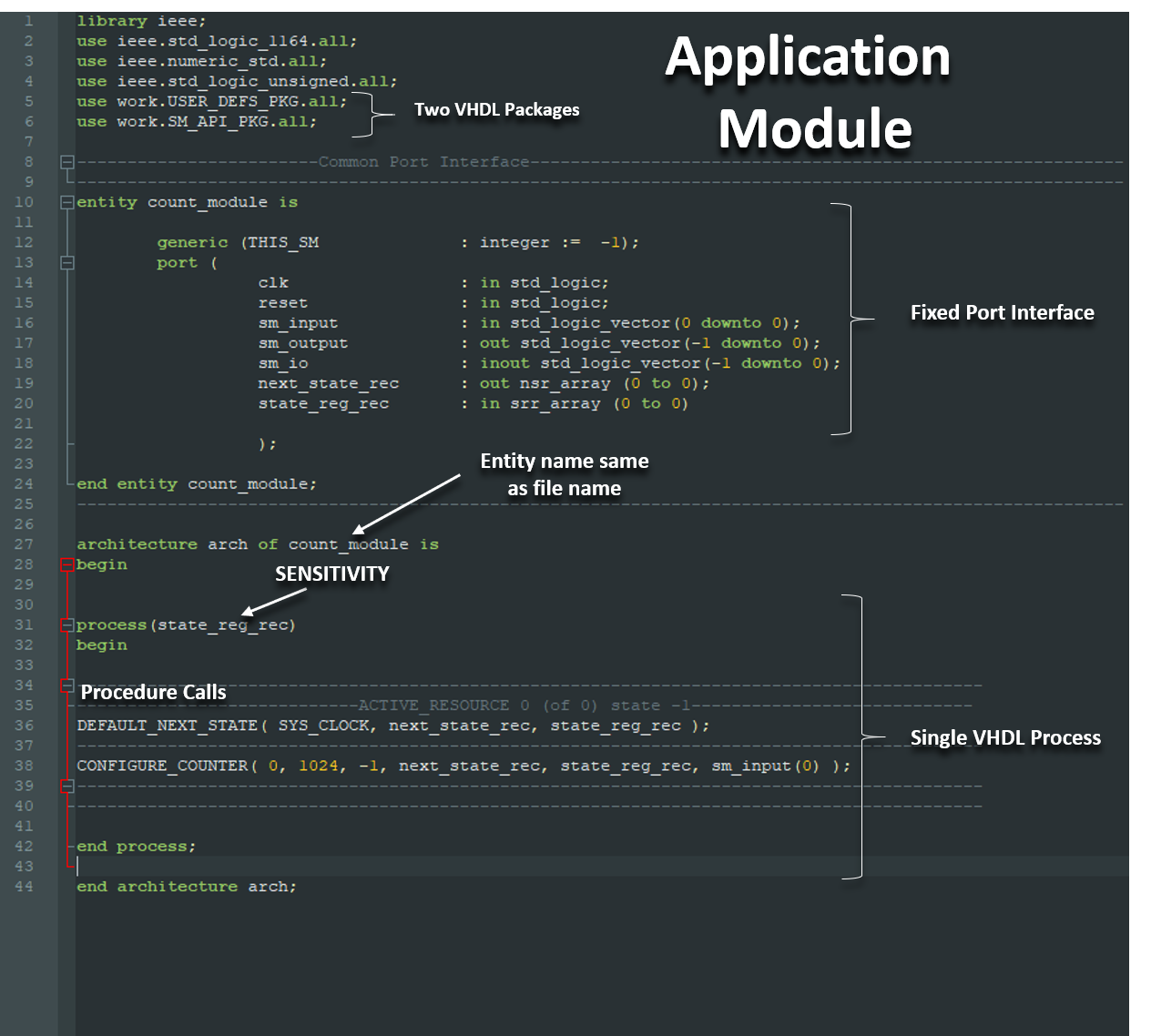
Let's take a look a the VHDL code that implements this behavior with our design pattern. The application module calls a procedure named 'configure_counter' and the input pin, sm_input(0), is routed to the last argument of the call.  Because a state machine is used as a facade object to abstract away the counter specifics, and any changes to sm_input(0) act as events to control the counter, the entire application module behaves as an event driven state machine.
There are a couple of things we should note about the code. The first thing is that at VHDL compile time, based on the name of the procedure call 'configure_counter', it is known that the hardware will be a counter. There is no 'runtime action' at play here.  The second thing to note is that every API procedure call requires the two parameters, next_state_rec, and state_reg_rec, which are wired directly from the port.  From the modules prospective, the next state logic is an output where the the state register logic is an input.  All of the parameters of the procedure call except for state_reg_rec are used to assemble the next state logic (shown in blue and purple). The next state logic gets passed out of the application module fixed port and becomes an input to the framework module. The framework module, in turn uses the next state logic presented to it as an input and creates the state registered logic as an output of the framework to become an input to the application module.
<aside class="d-flex align-items-center aside-xxx">
Added Value
Sed ut perspiciatis unde omnis iste natus error sit voluptatem accusantium doloremque laudantium, totam rem aperiam.

</aside> <aside class="d-flex align-items-center aside-xxx">

Added Value
Looking at the port this sm_input has the range (0 donwto 0 which gives us the one input).

</aside> <aside class="d-flex align-items-center aside-xxx">

Added Value
Hardware that can be inferred by a simple procedure call are infrastructure related components, in is how the framework achieves infrastructure reuse.

</aside> <aside class="d-flex flex-row align-items-center aside-xxx">

Added Value
Now from the framework modules prospective, it takes the next_state_logic, processes it and output the state_reg_rec signal. 

</aside> <aside class="d-flex flex-row align-items-center aside-xxx">

Added Value
together the next_state_logic, processes it and output the state_reg_rec signal make up our facade object 

</aside>

The Default Behavior Should Be the Most Useful Behavior

One of the most frustrating things about simulating an FPGA design is when you simulate the code and it just flatlines and doesn't do anything.  Say you missed wiring a single enable signal, you run your code and you get nothing. Small errors like this make it almost impossible to debug.

When creating our API, using default arguments, we try to prevent things like flatlining from happening.  That being said, lets take another look at the 'configure_counter' procedure call and this time lets imagine we forgot to wire sm_input(0) to the last parameter.
If we were to compile and simulate the design, the code may not work as desired, but the counter would still do something. We would see it free running and rolling over as it counts from 0 to 1023. Once we see this, it will be easy to know what we should fix. That behavior occurs because our choice was to make the default value for the count_en  to be '1', and the default value for the rollover_en to be '1'.

Continuing with our design pattern strategy to treat 'everything as a state machine', the default state of every hardware component inferred by procedure call is made up of two parts: 
<aside class="d-flex align-items-center aside-xxx">
Added Value
Sed ut perspiciatis unde omnis iste natus error sit voluptatem accusantium doloremque laudantium, totam rem aperiam.

</aside>

  1. The default values of the procedure call optional arguments (if any)
  2. The framework default values set by the 'default_next_state' procedure call.
If a procedure call supports optional arguments, those arguments would appear after the state_reg_rec parameter (shown in purple in the diagram). The default next state portion of the default state is set by the procedure call 'default_next_state'. These framework default values cannot be changed by the user and are necessary in order to prevent creating a latch for our next state logic.  
<aside class="d-flex align-items-center aside-xxx">
Added Value
The 'default next state' procedure call must always appear as the first procedure call in the process.

</aside>

Alias is Your Friend

Using VHDL aliases is one way to combat the annoying affects of having long signal names caused by using array and record data types. If we started with an array or record signal type, we could just use an alias to reference a specific array index or record field without the need to make both a signal declaration and a signal assignment.  When we use the design pattern, there is no way around having to interact with large data structures. Because VHDL provides aliases as a language feature, we should use an alias whenever the situation calls for a shorter signal name to promote readability.
<aside class="d-flex align-items-center aside-xxx">
Added Value
Sed ut perspiciatis unde omnis iste natus error sit voluptatem accusantium doloremque laudantium, totam rem aperiam.

</aside>

Integer Index, Count, and State

Another VHDL feature that the design pattern makes plenty use of is the ability to constrain integers. And not only do we use constrained integers, we prefer them over std_logic_vector if given a situational choice.  Although the main reason for using integers has to do with indexing arrays, the design pattern uses the integer data type also for counter values and state machine state. 
<aside class="d-flex align-items-center aside-xxx">
Added Value
if writign data to this modulele, the other module can call this module by its intenetiy name.

</aside>

Speaking of counters, let's revisit our example API call that uses to procedure call 'configure_counter'. Continuing on with our API design strategy of treating everything as a state machine, we have built some extra state machine functionality into our 'configure_counter' API call. 

Looking at the third parameter, we have set the transition state to -1.  The meaning of -1 in this context is we wish for the counter to just count, but not 'do anything' when the counter expires. Because the state machine states have the integer data type, we 'could' on the other hand, configure a state machine to change state when the rollover occurs.
<aside class="d-flex align-items-center aside-xxx">
Added Value
Although it is not clear from the counter example, there is a productivity advantage in choosing the state machine state type be an integer. We will see this when we begin using state machines.

</aside>

Productivity Should Come For Free

In looking a the code that implements our counter using the design pattern,  we were first interested in pointing out the notable things you expect to see.  Now we want to shift gears and point out some productivity increasing features based on things you don't see.
  • You don't see clock or reset being used
  • You don't see a signal declaration
  • You don't see an 'if-then-else' statement
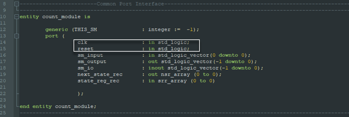
Although you don't see a clock or reset being used, we claim however, if the reset were to be asserted, that the counter value would be set to zero. We also claim that when the counter increments, it would do so on the rising edge of the clock.  The reason for this behavior is a culmination of our API and design pattern strategy to 'treat everything as a state machine', 'make default behavior useful', and we believe that productivity should come for free.

When a counter resets, shouldn't the count go to zero? When it increments, wouldn't it be on the rising edge? Since the motivation for our design pattern is to increase design productivity, we should not have to write extra code to specify some assumed operation. If its expected behavior, you should get that for free.

Another productivity enhancing byproduct that occurs when using the design pattern, is a substantial decrease in the number of 'infrastructure related signals' you need to declare. A while back in our discussion, we mentioned that the data structures that are used by the design pattern were large and that how the long names can be annoying.  But here is the up side.  Those long state_reg_rec signal names come from the framework as an input to the application module port. That means we get access to a large data structure  that we did not need to declare as a signal in our code.  We can just start coding our application module and pick off the portions of the state register that we would like to use and start using them.  Any portions of state register we use gets kept, and the rest of the large data structure just gets synthesized away.
<aside class="d-flex align-items-center aside-xxx">
Added Value
Infrastrure related signals are the signals relate to hardware that gets generated inside the framework module.

</aside>

When using the design pattern and requesting framework resources we rarely need to interact with the clock and the reset signal. That's a good thing, it saves us from having to write many of the dreaded 'if-then-else' statements. 
The clock and reset signals from the fixed port are needed when we create custom logic or to be passed to IP cores. Let's say that the FPGA developer needs a custom counter that increments on the clock falling edge and should be reset to exactly "010111" for some weird reason. That specific requirement is a good reason to write some RTL code to infer a specialized counter.

The takeaway here is that, the use of the API calls to infer hardware from the framework is optional. Productivity from infrastructure reuse happens when an application module can take advantage of the design pattern handing a general case not every specific use case. Once a VHDL entity conforms to the fixed port interface and becomes an application module, that module gets access to framework resources whether it uses them or not. If the application module chooses to use API calls to infer hardware, it is essentially productivity that the module gets for free. 

<aside class="d-flex align-items-center aside-xxx">
Added Value
It should be noted, that the use of API calls to infer hardware is a choice, but API calls are required for module-to-module interconnection

</aside>

</section> <section>

<header>

Logical Interconnection

</header>

Synchronous Communication Between Application Modules

Using the Fixed Port Flat Architecture Design pattern gives us the capability of utilizing framework resources, such as registers, counters and fifos through the use of an API.  Using the API increases FPGA design productivity due to fact that we do not need instantiate any components or write any RTL logic.  However, because our design pattern constrains the port of the application modules to have a fixed set of signals with the I/O signaling designed to FPGA pins, this implies that module-to-module interconnection must be routed through the framework module.  In addition, because the only interface we have to the the framework module is done through API calls, this implies that any and all information that gets sent module-to-module must be done through the API.

Back when we made our modifications to the software version of the facade design pattern, we added the ability to logically identify each application module by use of an integer. Without delving into all the details, this is how the logical identifier comes into play. 
Currently the design pattern supports three types of communication be tween between application modules.
  1. Point to Point Communication (Data Channel)
         ⇄ Fifo Communication
         ⇄ Data Exchange Register
  2. Shared Control Register (Control Channel)
  3. Event Broadcasting
<aside class="d-flex align-items-center aside-xxx">
Added Value
The fact that the modules have the same port interface and interconnection is done by the framework goes back to the fact the the architecture is 'flat'.

</aside>

Point to Point Data Path Communication

Fifo Communication

One use case where the ease of use our design pattern that can increase FPGA design productivity dramatically is in situations where the data path is clearly visible and operations can be performed by IP blocks daisy chained by fifos.  Consider the following signal processing chain:
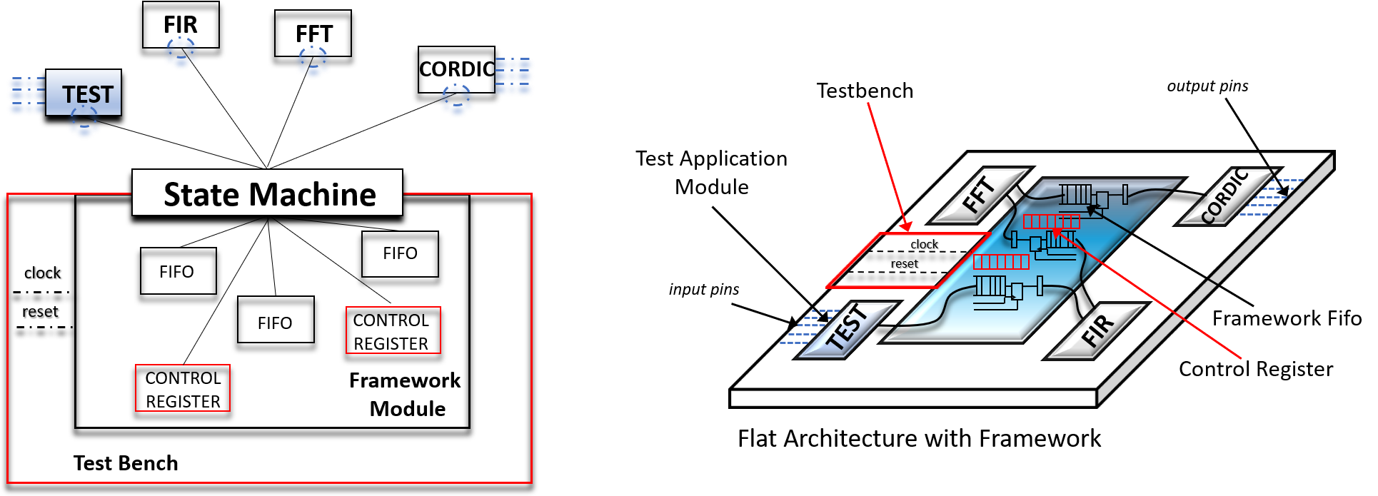
Now lets assume that we were to put each of these IP blocks into a separate .vhd file and utilize the design pattern framework module to logically interconnect the modules by use of a framework fifo. Let's also assume that we wanted to simulate the design and use  'our design pattern version of a test bench'. We would end up with a system that looks like the following.
The daisy chain connection between the modules is done by simple API calls. The first module (which may take some data from input pins) starts of with a write, where the intermediate modules perform a read from the module to their left, processes the data and then passes the data along to the module to its right. The module to the far right, the cordic_module only performs a read from the fft_module. We assume it does its cordic processing, and then passes whatever result to some output pins of the FPGA.
<aside class="d-flex align-items-center aside-xxx">
Added Value
Sed ut perspiciatis unde omnis iste natus error sit voluptatem accusantium doloremque laudantium, totam rem aperiam.

</aside> <aside class="d-flex align-items-center aside-xxx">

Added Value
The functionality of each module being a single process, loosly coupled and the possibility of any module accessing its own I/O pins without the need of modifying another moduel is the reason why the applicaiton modules behave like software microservices.

</aside> <aside class="d-flex align-items-center aside-xxx">

Added Value
See Notes on Implementation

</aside>

Data Exchange Register

As a by product of implementing, there exists an interesting case where the the application module uses the WRITE_FIFO_DATA procedure call but the fifo_write_en is set to '0' (do not write).  Data can still be placed on the register that is leading to the fifo buffer, but is not allowed to inter the buffer.  Since during implementation, we need the register anyway, with our design pattern, we allow that register data to cross the framework module to the destination module (if any).  Since there is no flow control, (once the channel is open) , that register only takes one clock cycle to cross through the framework module to its destination.
<aside class="d-flex align-items-center aside-xxx">
Added Value
If there was an issue with implementation it would be due to the virtue that the crossbar width must be set top the same width for all modules.  This is currently 32bit.

</aside>

Shared Control Register

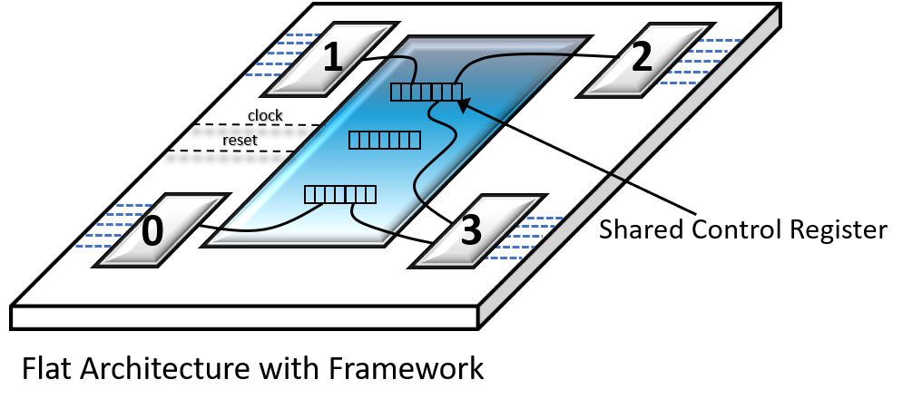
Using a fifo or data exchange register can used when data is to be sent between two modules. However, some applications require that multiple application modules have the capability of reading and writing data to one another. Using a point to point communication channel would be too restrictive. Because of this the design pattern implements a shared control register that can be used on each resource. The 'bus'  is used as a shared between any application modules that logically connect to it and the bus can be used for both reading an writing. The register is mediated by the framework module  and OR'd together in order to handle the case of multiple writers.
Using a shared control register, it is intended that a slice of the register be allocated to any application wishing to write.  Assuming another application module knows the indexes that are expected and the meaning of the data on another slice, then commination can be sent in a many to many fashion that way. Shared control registers allows for multiple clusters of modules to communicate to one another based on functionality.
<aside class="d-flex align-items-center aside-xxx">
Added Value
Sed ut perspiciatis unde omnis iste natus error sit voluptatem accusantium doloremque laudantium, totam rem aperiam.

</aside>

Event Broadcasting

One of the benefits of utilizing an API over traditional RTL programing is that procedural programing enhances the readability in the design. Given that the design pattern and API strategy is to treat everything as as an event driven state machine, in many instances the developer may enhance the readability of the design by using specific API calls to register for events or respond to an event. Although it is very possible to use a control register to write to a specific bit and have multiple application modules respond in some way,  using a control register would most likely need an 'if statement' to create the desired functionality. 

In general, using 'if statements' are frowned upon when using the design pattern. Because of this, when a transition is needed in response to an event, to make the intent clear, the design pattern has specific API calls to raise and/or event or respond to an event.
<aside class="d-flex align-items-center aside-xxx">
Added Value
Sed ut perspiciatis unde omnis iste natus error sit voluptatem accusantium doloremque laudantium, totam rem aperiam.

</aside>

</section> <section>

<header>

Simulating for the Design Pattern

</header>

Productivity While Testing

When we introduced 'The Fixed Port'  we said that our goals in creating the design pattern was to achieve "productivity of FPGA design by reducing development time at both the module level and system level".  Using the design pattern, we have achieved a pretty good level of decoupling from of the application modules from one another and from the rest of the system. By using a fixed port and a facade object,  we have confined ourselves to only use API calls in order to communicate between modules.

In order to simulate an FPGA design that uses our design pattern, we have essentially two options.
  • Use a testbenches file to instantiate the top level design and drive application module I/O pins with the testbench file
  • Use a testbenches file to instantiate the top level and drive signals internally from the API
Both options assume that the clock generation is done in the test bench file. The first option is of using a testbenches to drive the application module I/O pins no different that writing a test bench for a traditional hierarchical design that does not utilize the design pattern. The problem with this approach is that a custom test bench file needs to be written for ever design.
On the other hand,  because we are utilizing the Fixed Port Flat Architecture design pattern we another option.  What if, instead of using the testbench file to drive the application module I/O pins we were to choose to not drive the I/O pins at all. Instead, we could either add an TEST application module and use API calls from the control register in order to send logic levels that that simulate I/O pin behavior.  We would have to modify our application module code, to now 'pick off' control register bits, instead of signals from the fixed port. This is true. However,  what this buys for us is the ability to have a testbench file that that only drives the clock and the reset.  We never need to change it.
<aside class="d-flex align-items-center aside-xxx">
Added Value
Sed ut perspiciatis unde omnis iste natus error sit voluptatem accusantium doloremque laudantium, totam rem aperiam.

</aside>

</section> <section> <header class="justify-content-center banner-header theme-outline" dx-block="block">

VHDL Code Structure Using the Design Pattern

</header>
<CODE SNIPPET>

A Uniform Coding Structure

From a FPGA developers stand point, we need not care exactly how the Fixed Port Flat Architecture Design Pattern works, we just need to know how to set it up correctly and how to use the API. The setup process is scripted the use of SpeakHDL.  It is instructive however to look at the resultant VHDL code.  Using the design pattern that involves API calls, we end up with a uniform VHDL coding structure which we can design to.  There are a few things that are notable the VHDL code using the design pattern:
 Functionaility of the design pattern are brought to the developer thorught two VHDL packages. Due to the Fixed Port Constraint
  • Functionality of the design pattern are brought to the developer through the use of two non standard VHDL packages
  • The entity name is required to match the VHDL file name
  • The VHDL sensitivyt list is sensitive to the state register
  • In general there will only be a single VHDL process per file
<aside class="d-flex align-items-center aside-xxx">
Added Value
Sed ut perspiciatis unde omnis iste natus error sit voluptatem accusantium doloremque laudantium, totam rem aperiam.

</aside>

</section> <section> <header class="justify-content-center banner-header theme-outline" dx-block="block">

Creating an API for FPGA Hardware Development

</header>

Strategy for API Development

Attempting to create an API for FPGA hardware design is somewhat difficult because our abstractions and implementation are so tightly coupled. One thing to note when creating our API is that we are not changing the underlying complexity of FPGA design, we are trying to hide the complexity from the API caller by utilizing abstraction and structured levels of data organization. Due to our organizational scheme, we end up with very large data structures that we have to interact with.

Our challenge in trying to a creating a useable API for FPGA hardware development is threefold: 
  1. Understand the synthesizable HDL language features we have at our disposal
  2. Organize the data structures that we create in such a way that the end user can become the most productive
  3. Create procedure calls based on operations that can be used as building blocks in system design
Understanding the synthesizable HDL language features that we have at our disposal is most important because it will influence the data structures we create and the procedure calls we define. Interestingly enough, the VHDL language supports function and procedure overloading. The ability to have a single procedure call that can accept parameters of different data types and do different things based on that data type knowledge at compile time is extremely beneficial. Using this language feature to our advantage helps us to decrease the number of different procedure call names that the user will need to interact with.

Because, creating an API is more of an art than a science,  there will be instances where we could approach our data structuring in multiple ways.  Since our overall goal is to be come more productive FPGA developers, we describe the strategy we use for creating the API for our design pattern.
  • Treat everything as a synchronous state machine
  • Ensure the default behavior is the most useful behavior
  • Prefer indexing an array over a creating a new signal
  • Use aliases for readability
  • Use integer data types for index, count, and state
  • Have productivity come for free
<aside class="d-flex align-items-center aside-xxx">
Added Value
From a productivity stand point. We would rather end up with a small number of large data structures than a large number of small ones

</aside> <aside class="d-flex align-items-center aside-xxx">

Added Value
Procedure overloading is a form of static polymorphism. Also is benefical over verilog

</aside>

Everything Is A Synchronous State Machine

In development of the design pattern, we started using a state machine as a facade object.  Now, we take the state machine concept a step further and begin treating the application modules as event driven state machines. By doing this, it makes sense to keep the signal nomenclature explicit to make it clear that when using the design pattern, we are dealing with state machines. Thus our API procedure calls explicitly call out the next state logic and state register logic as their last two mandatory parameters.

To motivate our rationale as to why we should treat an application module as a state machine, let's start with an example where an application module has exactly one input pin that is used as the count enable to a framework counter
Let's take a look a the VHDL code that implements this behavior with our design pattern. The application module calls a procedure named 'configure_counter' and the input pin, sm_input(0), is routed to the last argument of the call.  Because a state machine is used as a facade object to abstract away the counter specifics, and any changes to sm_input(0) act as events to control the counter, the entire application module behaves as an event driven state machine.
There are a couple of things we should note about the code. The first thing is that at VHDL compile time, based on the name of the procedure call 'configure_counter', it is known that the hardware will be a counter. There is no 'runtime action' at play here.  The second thing to note is that every API procedure call requires the two parameters, next_state_rec, and state_reg_rec, which are wired directly from the port.  From the modules prospective, the next state logic is an output where the the state register logic is an input.  All of the parameters of the procedure call except for state_reg_rec are used to assemble the next state logic (shown in blue and purple). The next state logic gets passed out of the application module fixed port and becomes an input to the framework module. The framework module, in turn uses the next state logic presented to it as an input and creates the state registered logic as an output of the framework to become an input to the application module.
<aside class="d-flex align-items-center aside-xxx">
Added Value
Sed ut perspiciatis unde omnis iste natus error sit voluptatem accusantium doloremque laudantium, totam rem aperiam.

</aside> <aside class="d-flex align-items-center aside-xxx">

Added Value
Looking at the port this sm_input has the range (0 donwto 0 which gives us the one input).

</aside> <aside class="d-flex align-items-center aside-xxx">

Added Value
Hardware that can be inferred by a simple procedure call are infrastructure related components, in is how the framework achieves infrastructure reuse.

</aside> <aside class="d-flex flex-row align-items-center aside-xxx">

Added Value
Now from the framework modules prospective, it takes the next_state_logic, processes it and output the state_reg_rec signal. 

</aside> <aside class="d-flex flex-row align-items-center aside-xxx">

Added Value
together the next_state_logic, processes it and output the state_reg_rec signal make up our facade object 

</aside>

The Default Behavior Should Be the Most Useful Behavior

One of the most frustrating things about simulating an FPGA design is when you simulate the code and it just flatlines and doesn't do anything.  Say you missed wiring a single enable signal, you run your code and you get nothing. Small errors like this make it almost impossible to debug.

When creating our API, using default arguments, we try to prevent things like flatlining from happening.  That being said, lets take another look at the 'configure_counter' procedure call and this time lets imagine we forgot to wire sm_input(0) to the last parameter.
If we were to compile and simulate the design, the code may not work as desired, but the counter would still do something. We would see it free running and rolling over as it counts from 0 to 1023. Once we see this, it will be easy to know what we should fix. That behavior occurs because our choice was to make the default value for the count_en  to be '1', and the default value for the rollover_en to be '1'.

Continuing with our design pattern strategy to treat 'everything as a state machine', the default state of every hardware component inferred by procedure call is made up of two parts: 
<aside class="d-flex align-items-center aside-xxx">
Added Value
Sed ut perspiciatis unde omnis iste natus error sit voluptatem accusantium doloremque laudantium, totam rem aperiam.

</aside>

  1. The default values of the procedure call optional arguments (if any)
  2. The framework default values set by the 'default_next_state' procedure call.
If a procedure call supports optional arguments, those arguments would appear after the state_reg_rec parameter (shown in purple in the diagram). The default next state portion of the default state is set by the procedure call 'default_next_state'. These framework default values cannot be changed by the user and are necessary in order to prevent creating a latch for our next state logic.  
<aside class="d-flex align-items-center aside-xxx">
Added Value
The 'default next state' procedure call must always appear as the first procedure call in the process.

</aside>

Prefer Indexing an Array Over a Creating a New Signal

Using a state machine as a facade object, we now have a generic interface to the underlying hardware components made available to us by the framework module. If our port interface is fixed, that means state_reg_rec is the only input signal that is routed from the framework module to access the hardware components. We need to create a data structure flexible enough to accommodate a variable number of different hardware components with the possibility of adding more components in the future. 
The application module is presented with the state_reg_rec signal at is input which is fixed by the port signaling restriction, but how we choose to logically organize the hardware components on the framework side is us. Inside the framework we chose to logically group the available the hardware components into what we call an 'array of resources'.  Each resource element contains (for now):
  • A single state machine
  • A single fifo (receive buffer)
  • A single control register
  • An array of counters
  • An array of edge detectors
  • Framework crossbar logical circuitry (synchronous)
This means that state_reg_rec is obviously a pretty large data structure. Even in this extremely simple example with a single counter, the integer value that we read (shown in red color) , state_reg_rec(0).counter(0).value, is a data structure comprised of two array of record signals.  Not only is state_reg_rec an array of records, 'counter'  is also an array of records.

When developing the API, the decision to make both state_reg_rec and counter arrays had mostly to do with how to handle some implementation details on the framework side. Using an array data type gives us flexibility on the number of components we can create inside the framework module using the same looping structure. On the application module side, using arrays also gives us the flexibility of generating as many state registers or as many counters as we would like. The one drawback, however, is that it leads to a state register signal that has a long signal name. 

Over all, the benefits of having the capability of generating more hardware outweighs the minor drawback of creating longer names. Given a choice, we should prefer to index an array data structure rather then creating a new signal name.
<aside class="d-flex align-items-center aside-xxx">
Added Value
SpeakHDL actually uses the indexing on the arrays to help structure where the actual code should be written on the page

</aside> <aside class="d-flex align-items-center aside-xxx">

Added Value
Although implementing a protocol with the framework is possible, we feel like it would be a very bad idea.  The design pattern is mean to give the user the ability to create using building blocks.

</aside> <aside class="d-flex align-items-center aside-xxx">

Added Value
When we refer to requesting a resource from the framework, we mean part our all of the available grouping of hardware

</aside> <aside class="d-flex align-items-center aside-xxx">

Added Value
The reason why counters and edge detectors were made into arrays, is because we use these basic hardware elements to build up larger hardware components, so we may need more of them.

</aside>

Alias is Your Friend

Using VHDL aliases is one way to combat the annoying affects of having long signal names caused by using array and record data types. If we started with an array or record signal type, we could just use an alias to reference a specific array index or record field without the need to make both a signal declaration and a signal assignment.  When we use the design pattern, there is no way around having to interact with large data structures. Because VHDL provides aliases as a language feature, we should use an alias whenever the situation calls for a shorter signal name to promote readability.
<aside class="d-flex align-items-center aside-xxx">
Added Value
Sed ut perspiciatis unde omnis iste natus error sit voluptatem accusantium doloremque laudantium, totam rem aperiam.

</aside>

Integer Index, Count, and State

Another VHDL feature that the design pattern makes plenty use of is the ability to constrain integers. And not only do we use constrained integers, we prefer them over std_logic_vector if given a situational choice.  Although the main reason for using integers has to do with indexing arrays, the design pattern uses the integer data type also for counter values and state machine state. 
<aside class="d-flex align-items-center aside-xxx">
Added Value
if writign data to this modulele, the other module can call this module by its intenetiy name.

</aside>

Speaking of counters, let's revisit our example API call that uses to procedure call 'configure_counter'. Continuing on with our API design strategy of treating everything as a state machine, we have built some extra state machine functionality into our 'configure_counter' API call. 

Looking at the third parameter, we have set the transition state to -1.  The meaning of -1 in this context is we wish for the counter to just count, but not 'do anything' when the counter expires. Because the state machine states have the integer data type, we 'could' on the other hand, configure a state machine to change state when the rollover occurs.
<aside class="d-flex align-items-center aside-xxx">
Added Value
Although it is not clear from the counter example, there is a productivity advantage in choosing the state machine state type be an integer. We will see this when we begin using state machines.

</aside>

Productivity Should Come For Free

In looking a the code that implements our counter using the design pattern,  we were first interested in pointing out the notable things you expect to see.  Now we want to shift gears and point out some productivity increasing features based on things you don't see.
  • You don't see clock or reset being used
  • You don't see a signal declaration
  • You don't see an 'if-then-else' statement
Although you don't see a clock or reset being used, we claim however, if the reset were to be asserted, that the counter value would be set to zero. We also claim that when the counter increments, it would do so on the rising edge of the clock.  The reason for this behavior is a culmination of our API and design pattern strategy to 'treat everything as a state machine', 'make default behavior useful', and we believe that productivity should come for free.

When a counter resets, shouldn't the count go to zero? When it increments, wouldn't it be on the rising edge? Since the motivation for our design pattern is to increase design productivity, we should not have to write extra code to specify some assumed operation. If its expected behavior, you should get that for free.

Another productivity enhancing byproduct that occurs when using the design pattern, is a substantial decrease in the number of 'infrastructure related signals' you need to declare. A while back in our discussion, we mentioned that the data structures that are used by the design pattern were large and that how the long names can be annoying.  But here is the up side.  Those long state_reg_rec signal names come from the framework as an input to the application module port. That means we get access to a large data structure  that we did not need to declare as a signal in our code.  We can just start coding our application module and pick off the portions of the state register that we would like to use and start using them.  Any portions of state register we use gets kept, and the rest of the large data structure just gets synthesized away.
<aside class="d-flex align-items-center aside-xxx">
Added Value
Infrastrure related signals are the signals relate to hardware that gets generated inside the framework module.

</aside>

When using the design pattern and requesting framework resources we rarely need to interact with the clock and the reset signal. That's a good thing, it saves us from having to write many of the dreaded 'if-then-else' statements. 
The clock and reset signals from the fixed port are needed when we create custom logic or to be passed to IP cores. Let's say that the FPGA developer needs a custom counter that increments on the clock falling edge and should be reset to exactly "010111" for some weird reason. That specific requirement is a good reason to write some RTL code to infer a specialized counter.

The takeaway here is that, the use of the API calls to infer hardware from the framework is optional. Productivity from infrastructure reuse happens when an application module can take advantage of the design pattern handing a general case not every specific use case. Once a VHDL entity conforms to the fixed port interface and becomes an application module, that module gets access to framework resources whether it uses them or not. If the application module chooses to use API calls to infer hardware, it is essentially productivity that the module gets for free. 

<aside class="d-flex align-items-center aside-xxx">
Added Value
It should be noted, that the use of API calls to infer hardware is a choice, but API calls are required for module-to-module interconnection

</aside>

</section> <section>

Logical Interconnection

Synchronous Communication Between Application Modules

Using the Fixed Port Flat Architecture Design pattern gives us the capability of utilizing framework resources, such as registers, counters and fifos through the use of an API.  Using the API increases FPGA design productivity due to fact that we do not need instantiate any components or write any RTL logic.  However, because our design pattern constrains the port of the application modules to have a fixed set of signals with the I/O signaling designed to FPGA pins, this implies that module-to-module interconnection must be routed through the framework module.  In addition, because the only interface we have to the the framework module is done through API calls, this implies that any and all information that gets sent module-to-module must be done through the API.

Back when we made our modifications to the software version of the facade design pattern, we added the ability to logically identify each application module by use of an integer. Without delving into all the details, this is how the logical identifier comes into play. 
Currently the design pattern supports three types of communication be tween between application modules.
  1. Point to Point Communication (Data Channel)
         ⇄ Fifo Communication
         ⇄ Data Exchange Register
  2. Shared Control Register (Control Channel)
  3. Event Broadcasting
<aside class="d-flex align-items-center aside-xxx">
Added Value
The fact that the modules have the same port interface and interconnection is done by the framework goes back to the fact the the architecture is 'flat'.

</aside>

Point to Point Data Path Communication

Fifo Communication
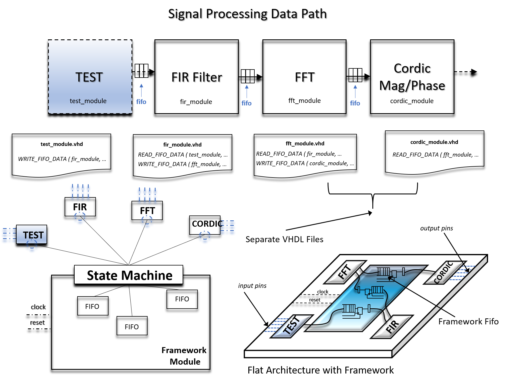
One use case where the ease of use our design pattern that can increase FPGA design productivity dramatically is in situations where the data path is clearly visible and operations can be performed by IP blocks daisy chained by fifos.  Consider the following signal processing chain:
Now lets assume that we were to put each of these IP blocks into a separate .vhd file and utilize the design pattern framework module to logically interconnect the modules by use of a framework fifo. Let's also assume that we wanted to simulate the design and use  'our design pattern version of a test bench'. We would end up with a system that looks like the following.
The daisy chain connection between the modules is done by simple API calls. The first module (which may take some data from input pins) starts of with a write, where the intermediate modules perform a read from the module to their left, processes the data and then passes the data along to the module to its right. The module to the far right, the cordic_module only performs a read from the fft_module. We assume it does its cordic processing, and then passes whatever result to some output pins of the FPGA.
<aside class="d-flex align-items-center aside-xxx">
Added Value
Sed ut perspiciatis unde omnis iste natus error sit voluptatem accusantium doloremque laudantium, totam rem aperiam.

</aside> <aside class="d-flex align-items-center aside-xxx">

Added Value
The functionality of each module being a single process, loosly coupled and the possibility of any module accessing its own I/O pins without the need of modifying another moduel is the reason why the applicaiton modules behave like software microservices.

</aside> <aside class="d-flex align-items-center aside-xxx">

Added Value
See Notes on Implementation

</aside>

Data Exchange Register

As a by product of implementing, there exists an interesting case where the the application module uses the WRITE_FIFO_DATA procedure call but the fifo_write_en is set to '0' (do not write).  Data can still be placed on the register that is leading to the fifo buffer, but is not allowed to inter the buffer.  Since during implementation, we need the register anyway, with our design pattern, we allow that register data to cross the framework module to the destination module (if any).  Since there is no flow control, (once the channel is open) , that register only takes one clock cycle to cross through the framework module to its destination.
<aside class="d-flex align-items-center aside-xxx">
Added Value
If there was an issue with implementation it would be due to the virtue that the crossbar width must be set top the same width for all modules.  This is currently 32bit.

</aside>

Shared Control Register

Using a fifo or data exchange register can used when data is to be sent between two modules. However, some applications require that multiple application modules have the capability of reading and writing data to one another. Using a point to point communication channel would be too restrictive. Because of this the design pattern implements a shared control register that can be used on each resource. The 'bus'  is used as a shared between any application modules that logically connect to it and the bus can be used for both reading an writing. The register is mediated by the framework module  and OR'd together in order to handle the case of multiple writers.
Using a shared control register, it is intended that a slice of the register be allocated to any application wishing to write.  Assuming another application module knows the indexes that are expected and the meaning of the data on another slice, then commination can be sent in a many to many fashion that way. Shared control registers allows for multiple clusters of modules to communicate to one another based on functionality.
<aside class="d-flex align-items-center aside-xxx">
Added Value
Sed ut perspiciatis unde omnis iste natus error sit voluptatem accusantium doloremque laudantium, totam rem aperiam.

</aside>

Event Broadcasting

One of the benefits of utilizing an API over traditional RTL programing is that procedural programing enhances the readability in the design. Given that the design pattern and API strategy is to treat everything as as an event driven state machine, in many instances the developer may enhance the readability of the design by using specific API calls to register for events or respond to an event. Although it is very possible to use a control register to write to a specific bit and have multiple application modules respond in some way,  using a control register would most likely need an 'if statement' to create the desired functionality. 

In general, using 'if statements' are frowned upon when using the design pattern. Because of this, when a transition is needed in response to an event, to make the intent clear, the design pattern has specific API calls to raise and/or event or respond to an event.
<aside class="d-flex align-items-center aside-xxx">
Added Value
Sed ut perspiciatis unde omnis iste natus error sit voluptatem accusantium doloremque laudantium, totam rem aperiam.

</aside>

</section> <section>

Simulating for the Design Pattern

Productivity While Testing

When we introduced 'The Fixed Port'  we said that our goals in creating the design pattern was to achieve "productivity of FPGA design by reducing development time at both the module level and system level".  Using the design pattern, we have achieved a pretty good level of decoupling from of the application modules from one another and from the rest of the system. By using a fixed port and a facade object,  we have confined ourselves to only use API calls in order to communicate between modules.

In order to simulate an FPGA design that uses our design pattern, we have essentially two options.
  • Use a testbenches file to instantiate the top level design and drive application module I/O pins with the testbench file
  • Use a testbenches file to instantiate the top level and drive signals internally from the API
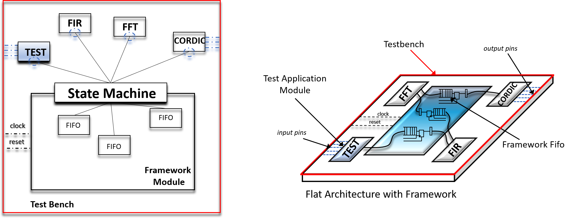
Both options assume that the clock generation is done in the test bench file. The first option is of using a testbenches to drive the application module I/O pins no different that writing a test bench for a traditional hierarchical design that does not utilize the design pattern. The problem with this approach is that a custom test bench file needs to be written for ever design.
On the other hand,  because we are utilizing the Fixed Port Flat Architecture design pattern we another option.  What if, instead of using the testbench file to drive the application module I/O pins we were to choose to not drive the I/O pins at all. Instead, we could either add an TEST application module and use API calls from the control register in order to send logic levels that that simulate I/O pin behavior.  We would have to modify our application module code, to now 'pick off' control register bits, instead of signals from the fixed port. This is true. However,  what this buys for us is the ability to have a testbench file that that only drives the clock and the reset.  We never need to change it.
<aside class="d-flex align-items-center aside-xxx">
Added Value
Sed ut perspiciatis unde omnis iste natus error sit voluptatem accusantium doloremque laudantium, totam rem aperiam.

</aside>

</section>

</article> <script src="https://cdnjs.cloudflare.com/ajax/libs/jquery/3.5.1/jquery.min.js"></script> <script src="https://cdn.jsdelivr.net/npm/bootstrap@5.2.3/dist/js/bootstrap.bundle.min.js"></script> <script src="assets/js/bss_custom_js.js"></script> <script src="https://unpkg.com/@bootstrapstudio/bootstrap-better-nav/dist/bootstrap-better-nav.min.js"></script> </body>

</html>