Architectural Framework
Architectural Framework
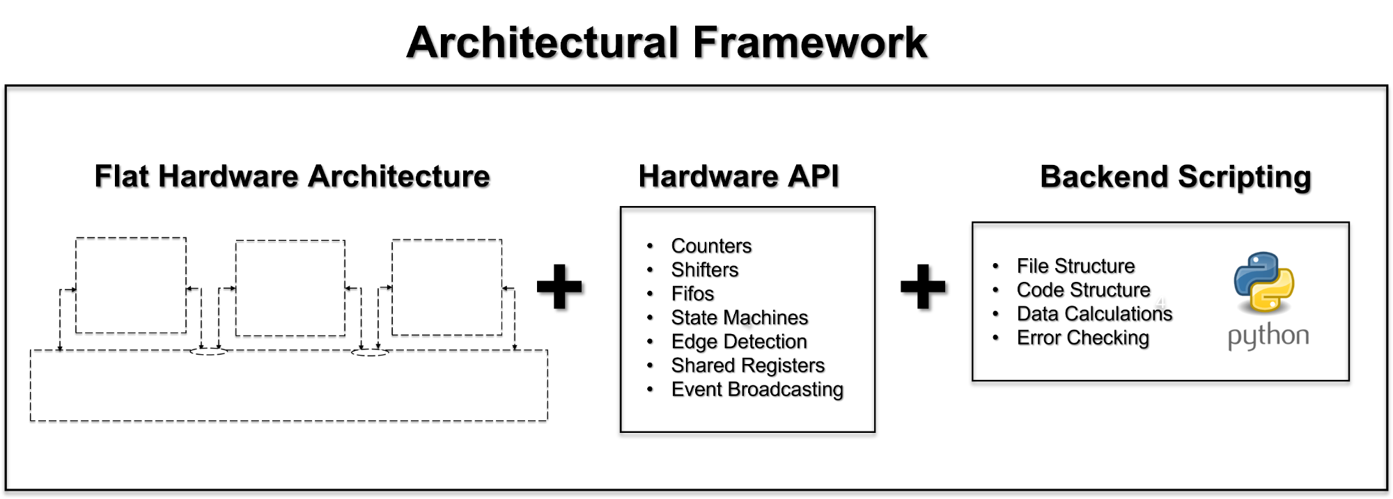
With SpeakHDL, an architectural framework consists of :
- a flat design architecture
- a hardware API
- the capability to perform scripting
Although any one of the three elements has the possibility of incrementally reducing development time, it is their use in tandem which provides the most design productivity. A flat architecture serves as a template for a design, while the API encapsulates the operations which can be performed within the architecture, and scripting provides a way to easily setup the and validate architecture.
Architectural Framework
flat_architecture
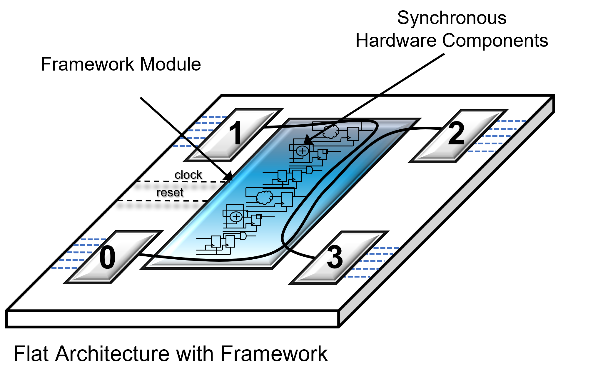
Flat Architecture
SpeakHDL utilizes a flat design architecture which differs from the traditional hierarchical architecture that is typically found in FPGA design. Flattening the architecture offers an immediate opportunity for FPGA design simplification. This is due to the fact that all modules appearing on a flat architectural level are inherently decoupled from any sub-component dependencies. A flat design architecture also makes the FPGA design problem much more tractable, both from a graphical stand point and from a coding stand point. SpeakHDL takes advantage of this by introducing a centralized framework module to manage the hardware resources for all application modules that appear on the same architectural level. Introduction of a framework module is the key step in making procedural programming useful for FPGA design.
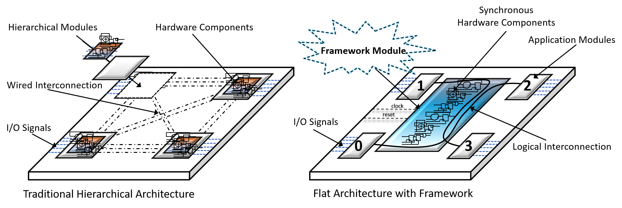
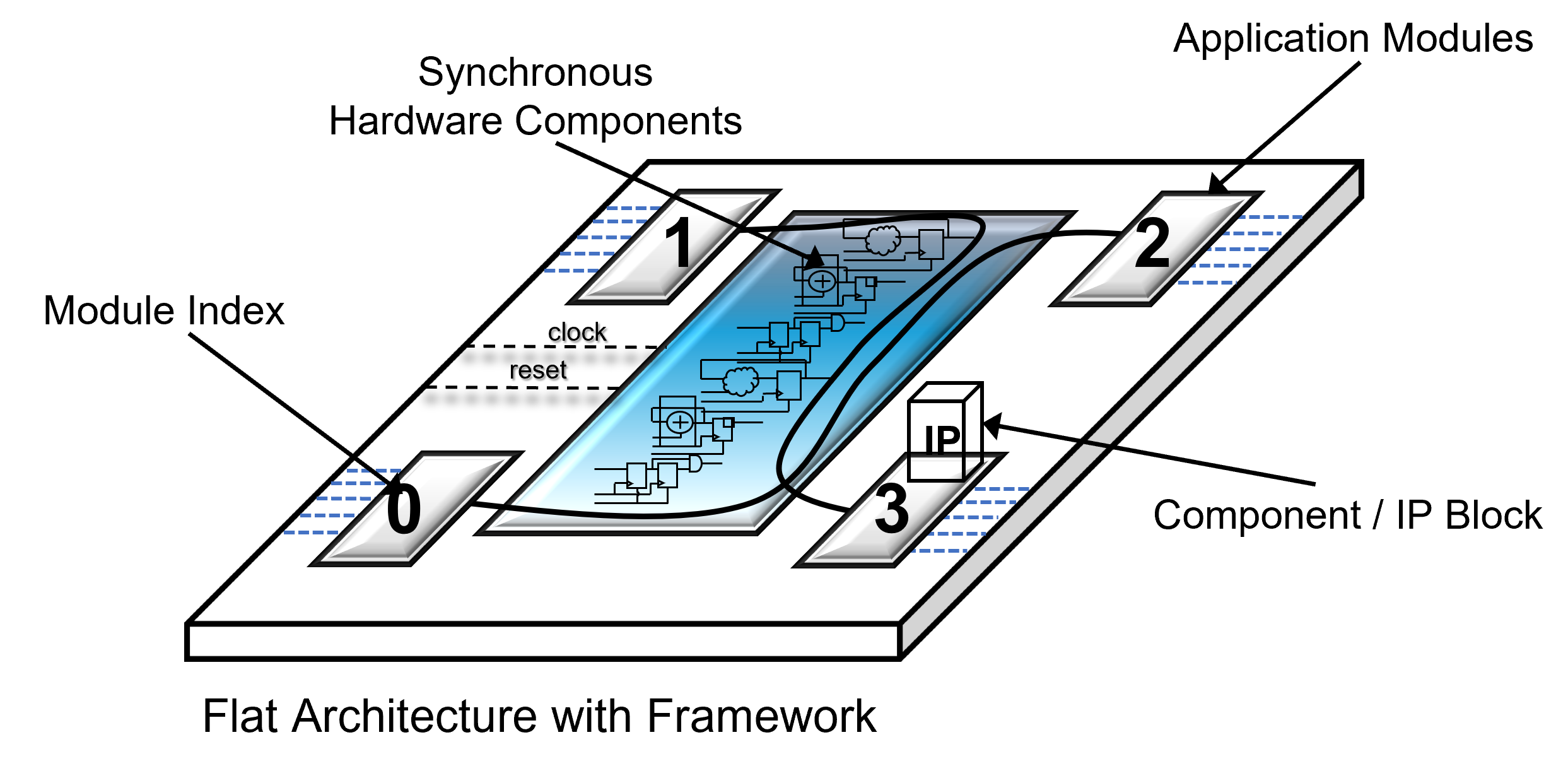
Application Module
Application Module
An application module is a VHDL entity that adheres to the common port interface required for use in the design pattern. The port interface contains (7) signals, two of which are the
system clock and reset signal
. In addition, each application module is assigned a
VHDL generic constant
module index for identification purposes and is connected to the framework module through its
next_state_rec
and
state_reg_rec
signals which make up the façade object in the
façade design pattern
. When an application module makes a procedure call, it is really a request to the framework to configure a synchronous hardware component (such as counter or fifo) on it's behalf. Application modules can be logically connected to one another by way of the framework module and data can be passed back and forth using a framework shared register or framework fifo.
Application Module
Application Module
Application Module Common Port Interface
Application Module
Application Module
What makes an application module different than a normal VHDL entity is that an application module has the following restrictions:
An application module:
- always resides at the top level of the FPGA design hierarchy
- always has the same port interface
- can instantiate components, but is never intended to be instantiated as a component
- can only communicate with other application modules by using procedure calls
- implements very little synchronous logic aside from logic generated by component instantiations
Framework Module
Framework Module
The framework module is a VHDL entity that acts as a centralized distributer of synchronous hardware resources (such as a fifos, counter, registers). When a procedure call is made, an application module configures a hardware resource combinatorically through its
next_state_rec
signal, and the framework module returns registered logic by way of the
state_reg_rec
signal. During synthesis, it is the framework module that actually implements the logic that is requested by the application modules when a procedure call is made.
In addition, the framework module handles the clock and reset signals for the requested resource. This is very productive for FPGA design. By consolidating the clock and reset signal into the framework module, application modules are not required to explicitly manipulate the clock and reset for hardware resources that are configured by API call.
The purpose of the framework module is to:
- act as a call center that receives API calls from all application modules
- handle the clock and reset for all framework resources
- infer and ' return ' values from hardware resources (such as counters, fifos, state machines, ect..) that are requested by application module
- perform interconnection between application modules
Framework Module
framework_resources
Framework Resources
In SpeakHDL, the term framework resources or hardware resources relate to both:
- the hardware components such as fifos, counters, state machines, and registers that are configured by procedure calls
- the VHDL array of records data structure that is utilized in procedure calls to organize those components
Framework Resource Hardware Components
Inside the framework module, each hardware component is
not
managed individually. Instead, the framework module bundles hardware components into a
groups of components called resources
. A
single
framework resource contains a state machine,
a chained hardware counter used for state transition timing, a receive fifo buffer, a shared register, a left and right shift register, an array of general purpose counters, an array of edge detectors, and an array of event signals.
The framework module contains an
array
of these bundled resources.

Framework Resource VHDL Data Structure
When making procedure calls, each framework resource is referenced an index of an
array of records
data structure named
state_reg_rec
. That is,
state_reg_rec(0)
refers to hardware components on
resource 0
and
state_reg_rec(1)
refers to hardware components on
resource 1
, ect.
Consider the following API Calls.
framework_resources
framework_resources
framework_resources
framework_resources
Resource Index and Resource Domain
Each enabled application module is assigned an array of framework resources . Resource 0 , which is the name given to the 0th index of the state_reg_rec array is presumed to always be utilized. However, using procedure calls, it is possible to specify higher index values of the framework resource array to configure hardware components.
SpeakHDL provides a procedure call named RESOURCE_SELECT in order for the developer to specify which resource index and clock domain a hardware component should be configured on. Any procedure calls that appear after the RESOURCE_SELECT procedure call with the specified resource index, M, configure hardware components on that resource index.
Framework hardware resources can be configured either on the same clock domain or on
separate clock domains
. When not necessary to differentiate, the terms
resource_index
and
resource domain
can be used interchangeably and are used to identify a grouping of hardware components that are configured by procedure calls with the
same
resource index, M, on the same clock domain.
For example, consider the following API calls:
framework_resources
- Note
- When no explicit resource index, M, is specified for state_reg_rec when making a procedure call, it is assumed to be resource index 0.
framework_resources
framework_resources
framework_resources
framework_resources
framework_resources
Module Index and ' this_module '
When making procedure calls, the developer need not be concerned with the absolute value of the module_index since the value can vary based on the number of enabled application modules and how many resource domains are utilized. What is of importance however, is that the module_index value consistently aligns with resource 0 , which is the first index of the array of resources assigned to the respective application.
framework_resources
framework_resources
Module Resource Value/ Module Offset Value
framework_resources
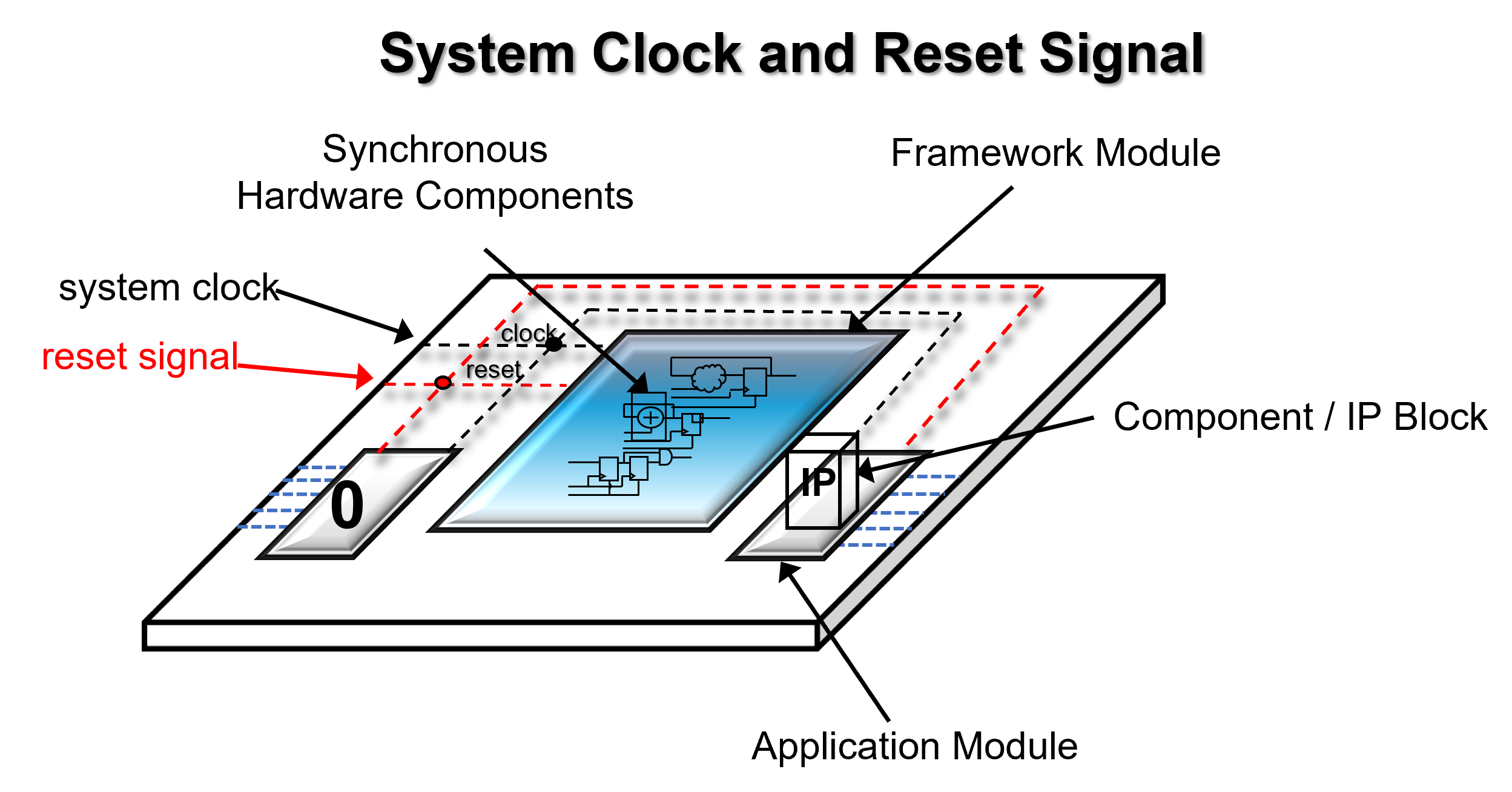
System Clock and Reset Signal
System Clock and Reset Signal
SpeakHDL requires that an FPGA design have a system clock signal and a global reset signal and also have an FPGA pin location assigned to each of them. When the reset signal is asserted, the framework module handles the responsibilities of resetting any hardware configured by procedure calls (counters, fifos, state machines, ect). Thus the developer is only responsible for resetting logic that gets inferred within an application module. This typically results in the clock and reset signals just being routed to components and IP blocks. After the reset is asserted, it is ensured that on the next rising edge of the system clock the following will occur:
- all counter values will be reset to zero
- all state machines will be reset to state zero
- all shift registers will be reset to zero
- all internal fifo element counters will be reset to zero and their read/write counters reset their default state (after two clock cycles)
- all shared registers will be reset to the default shared register polarity
Although it is not displayed on most diagrams, the system clock and reset signal are fanned out from the FPGA input pins to the framework module and to all application modules. However, the clock and reset signal need not be used within and application module to achieve the functionality provided by API calls. Instead, a developer may choose to make use of the implicit reset value of framework hardware components.
An example of taking advantage of an implicit reset value can be seen with the LED blink example . Inside the code, there is no reference to what the state of the LEDs should be upon reset. However because it is known that all framework counter values will be set to zero on system reset, the comparison logic has it such that the LEDs are off when the reset is asserted.
On the other hand, a user may choose to be more explicit as to what value output signals should be driven to upon system reset. A developer may choose to utilize the value of the reset signal directly or may use the initial value of the state register when setting combinatorial output signals. When there is a state machine already in use, it may make sense to drive output signals to a known state when state_reg = 0 .
Explicit Use of the Reset Signal
System Clock and Reset Signal
System Clock and Reset Signal
Use of the Initial Value of the State Register
System Clock and Reset Signal
System Clock and Reset Signal
- Warning
- An error will be displayed if the clk_pin and reset_pin are not given an FPGA pin location within the config_file.
System Clock and Reset Signal
Unassigned Clock and Reset Pin Locations
In order to synthesize the design, SpeakHDL requires a
clk_pin
location to be mapped to a clock oscillator on the development board and
reset_pin
location which can be mapped to any input pin location (button or switch, ect). Before any clock and reset location have been specified, SpeakHDL sets the default pin locations to be '<>' and prints these locations as VHDL comments next to the
port interface
of each application module.
When either the clock or reset pin locations are not specified, SpeakHDL will generate at least one
error
when the 'ok' command is given.
 Details for the errors and warnings can be viewed in the
ok.log
file. After pin location information for the clock and reset pin are given, SpeakHDL will show an
ok
status.
Details for the errors and warnings can be viewed in the
ok.log
file. After pin location information for the clock and reset pin are given, SpeakHDL will show an
ok
status.
![]()
ok.log Details for Unassigned Clock and Reset Pin Locations
System Clock and Reset Signal
System Clock and Reset Signal
- Note
- SpeakHDL generated errors related to pin locations only effect synthesis. If the design is only intended to be simulated and not synthesized, these pin location errors can be ignored.
System Clock and Reset Signal
A Uniform VHDL Code Layout Structure
A Uniform VHDL Code Layout Structure
One productivity enhancing feature used by SpeakHDL is the enforcement for a uniform VHDL code structure. Every application module follows the same text file structure from top to bottom. Each of the following VHDL code construct are displayed in order.
- Common Port Interface
- Component Declarations
- Alias and Signal Declarations
- Component Instantiations
- Output Signal Assignments
- Local Signal Assignments
- Parallel Procedure Calls
- Sequential Procedure Calls
A Uniform VHDL Code Layout Structure
A Uniform VHDL Code Layout Structure
No If-Then-Else Statements
No
"If-Then-Else"
Statements
SpeakHDL
does not
allow the
"if-then-else"
VHDL construct to appear inside of an application module. The constraint is by design and has a rather profound impact on how the design pattern is formulated. Due to the constraint, conditional logic operations must either be made using an "
when-else
" statement outside of the process construct or a
CONDITIONAL_TRANSITION
procedure call.
This requirement implicitly forces a developer to:
- formulate application module logic explicitly in terms of state transitions
- encapsulate all necessary RTL code inside of a component
- utilize only operations made available by the API
In addition, the lack of an
"if-then-else"
statement inside of a process implicitly prohibits the developer from inferring an RTL register due to the process. As a consequence, application modules typically only infer combinatorial logic if they do not instantiate any components.
Declarations and Data Types
Declarations and Data Types
SpeakHDL dramatically reduces the amount of signal declarations that are necessary when compared to traditional RTL style coding. One may look at the
next_state_rec
and
state_reg_rec
signals as a large number of pre-declared signals that a developer can immediately take advantage of. In addition, SpeakHDL
automatically creates signal declarations
for supported data types when signal assignments are made. In order to lower design complexity, SpeakHDL only support signal assignments for the most useful VHDL data types which are synthesizable. These data types include:
- std_logic
- std_logic_vector
- integer
State machines are defined to have an
integer
state type and all
std_logic_vector
signal assignments assumed to have a
downto
range.
VHDL constant
declarations (which are not a state machine state name) and VHDL
aliases for framework signals
are viewed as a form of configuration data and are captured in the local section of the config file.
- Note
- SpeakHDL defines a user defined std_logic_vector_array type and an integer_array type that can be useful for reading data from an external text file.
Declarations and Data Types
Declarations and Data Types
testbench_development
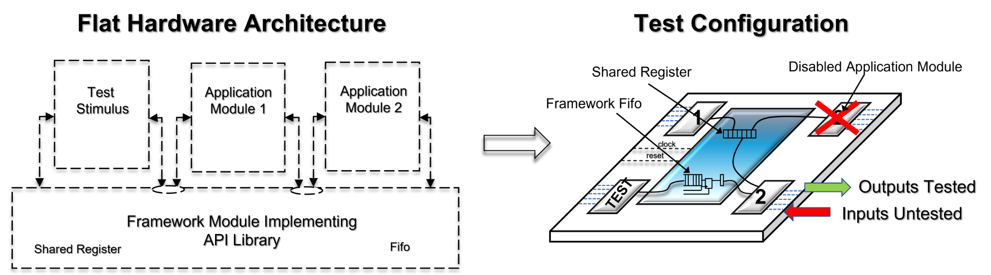
Testbench Development
With SpeakHDL, there is no real concept of a traditional HDL testbench. When using the design pattern, it is assumed that the API library has been rigorously tested and is operational. Thus, it is possible to use the API to generate stimulus waveforms for validation purposes. Due to the loose coupling of application modules, any application module can be used to generate test stimulus. One or two application module can be validated while the others are
set disabled
. Once a sufficient level of confidence is obtained in the tested portion, other application modules can be gradually added to the design.
One rationale for using the API to generate test stimulus, is that application modules must use the API for communication during normal operation anyway. Communication is always performed through the use of the SHARED_REGISTER or WRITE_FIFO_DATA procedure calls. In addition, the API can be used to simulate drivers for internal signals and output signals. However, the API cannot be used to simulate driving of input signals which enter from the FPGA pins. To simulate input signals, a traditional a traditional testbench must be created or a work-around must be performed.
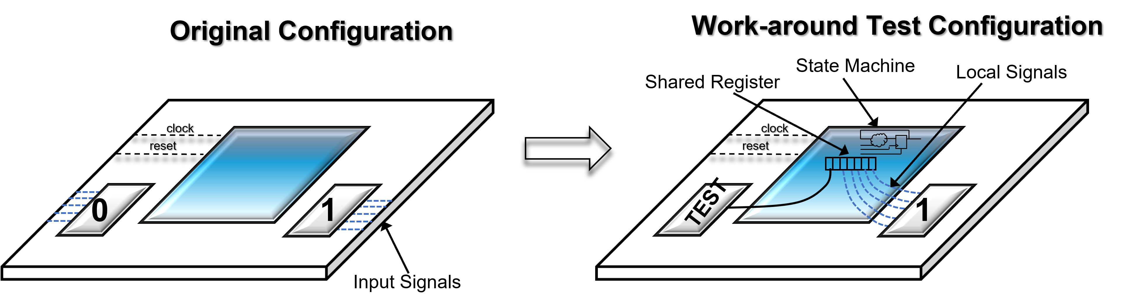
One possible work-around to simulate signals which originate from an external source would be to temporary replace the application module's input signals with local signals which are driven internally. After the replacement is made, the API once again can be utilized to exercise the logic. Local signals can be easily driven through the use of a state machine by creating transitions using timing functions .
testbench_development
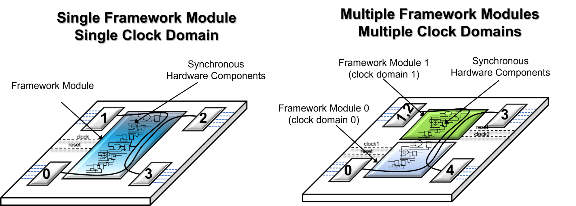
multiple_clock_domains
Multiple Clock Domains
With SpeakHDL there is at least one clock domain called the
sys_clk
domain with the default frequency of 100MHz if no other frequency is specified within the
configuration file
. Thus, there will be at least one framework module that handles the system clock and global reset signal. SpeakHDL handles multiple clock domains by through the use of multiple framework modules. Each framework module is responsible for handling the synchronous hardware components on its respective clock domain. To configure hardware that operates on separate clock domains, all that is needed is to make multiple calls to the
RESOURCE_SELECT
procedure on separate
resource indexes
and to give a clock frequency other than
sys_clk
as the first argument.